Views: 0 Author: Site Editor Publish Time: 2026-08-11 Origin: Site


The transition toward Permanent Magnet Synchronous Motor (PMSM) technology is driven by strict energy efficiency mandates, the demand for exceptionally quiet operation, and the need for smart, precise fluid control. While PMSMs offer superior energy savings and long-lasting reliability, their performance is highly sensitive to electrical input quality. Voltage instability, sags, and surges can compromise motor efficiency, disrupt constant pressure outputs, and in severe cases, cause irreversible rotor demagnetization or drive failure. Selecting the right equipment requires aligning the pump’s voltage tolerance, drive compatibility, and operating parameters with the facility's existing electrical infrastructure. We will look at how to evaluate voltage stability requirements, mitigate implementation risks, and ensure long-term reliability for your fluid handling systems. Proper power conditioning prevents premature wear and keeps your operations running without unexpected downtime.
Voltage Sensitivity: Permanent magnet motors require precise voltage regulation; fluctuations outside a specified tolerance (typically ±10%) can lead to thermal stress and efficiency losses.
Inherent Efficiency: Because PM rotors are magnetized at all times, they require no electrical power to induce a magnetic field, making them significantly more efficient than standard induction motors, especially at reduced speeds and partial loads.
Application-Specific Ranges: Low-voltage systems (e.g., 36V to 48V DC) are optimal for safe, residential, or light-commercial use, whereas an industrial permanent magnet pump requires robust 3-phase AC inputs managed by specialized Variable Frequency Drives (VFDs).
Drive Dependency: A permanent magnet pump cannot operate directly across the line (DOL); it requires a matched VFD or integrated smart controller to stabilize voltage, manage torque, and maintain a constant pressure output.
Risk Mitigation: Evaluating power quality—including harmonic distortion, long cable runs in submersible applications, and grid stability—is a mandatory step before finalizing procurement to avoid premature system failure.
Defining stable voltage requires looking at the actual power quality entering your facility. In fluid handling systems, stable voltage means minimal phase imbalance and strict adherence to IEEE 519 standards for harmonic distortion. A permanent magnet pump relies on precise electrical inputs to maintain exact speed and torque. When the incoming voltage fluctuates, the drive struggles to compensate, and the entire hydraulic system experiences erratic behavior. You will notice pressure drops and inconsistent flow rates at the discharge pipe.
Understanding how PMSM technology responds to voltage changes means looking at the motor's internal mechanics. The rotor contains rare-earth magnets and remains permanently magnetized. It draws no induction current from the stator to create a magnetic field. This specific design drastically reduces energy consumption compared to standard induction motors. However, it changes how the motor interacts with incoming power. Motor speed directly correlates with input voltage and back-electromotive force (Back-EMF). When input voltage drops, the drive must react immediately to keep the water flowing at the set point.
Voltage drops force the variable frequency drive to push higher stator current to the motor. The drive does this to maintain the required mechanical torque on the pump shaft. Higher current leads directly to increased copper losses. These losses generate excess heat inside the motor windings. Over time, this thermal stress bakes the wire insulation. It significantly shortens the operational lifespan of the equipment and leads to premature stator failure. When troubleshooting a stalled system, technicians often find the VFD fault log filled with undervoltage errors. This indicates the grid cannot supply the necessary power during peak demand hours.
Undervoltage presents immediate operational risks on the job site. The motor may stall if the voltage drops below the drive's minimum threshold. The system will fail to maintain steady water flow, causing pressure drops across the facility. Localized overheating becomes a severe issue during prolonged undervoltage events. The drive will eventually trigger a protective undervoltage fault. This causes unexpected downtime and requires a technician to manually reset the system after verifying the incoming power with a multimeter.
Overvoltage carries equally destructive consequences. Excessive voltage spikes risk immediate insulation breakdown in the motor windings. They can destroy the DC bus capacitors inside the drive instantly. High voltage also generates excessive thermal stress inside the motor housing. Extreme heat can push the rare-earth magnets past their Curie temperature. This causes irreversible demagnetization. Once demagnetized, the rotor loses its magnetic flux. The motor becomes useless and requires a complete replacement. You cannot repair a demagnetized rotor in the field.
Engineers categorize pump selection based on the operating voltage environment. Hydraulic demands and safety requirements dictate the appropriate electrical specifications. Different applications require vastly different power conditioning approaches. You cannot apply a one-size-fits-all electrical standard to every pumping station. The power quality at a remote agricultural site differs entirely from a commercial high-rise building.
Low-voltage systems operate between 36V and 48V DC. These systems prioritize human safety above all else. They use safe-touch personal safety voltage. You will find these units in residential boosters, large aquariums, and light commercial water features. They serve specific applications where water and electrical proximity poses a high risk to operators or the public. A 36V system eliminates the risk of fatal electric shock, making it ideal for environments with strict safety codes.
These low-voltage units offer excellent mechanical synergies. Manufacturers combine DC30-48V outputs with non-corrosive plastic pump components. These designs achieve high suction lift capabilities, often reaching up to 9.5 meters. They provide versatile, safe deployment options for tight spaces. These systems integrate wide-range input voltage controllers. The controllers convert standard fluctuating AC grid power into stable DC outputs for the motor. This conversion process isolates the sensitive DC motor from minor AC grid disturbances.
Industrial applications demand entirely different specifications. An industrial permanent magnet pump requires heavy-duty power inputs. High-capacity surface pumps operate on 230V, 460V, or higher 3-phase systems. Deep-well submersible groundwater pumps share these high-voltage requirements. These environments often feature heavy inductive loads from other machinery, such as large compressors or conveyors. Frequent voltage sags are common when these large loads start up across the facility. If you install a 460V pump on a grid that regularly dips to 415V, the drive will constantly fight to maintain the DC bus voltage.
Heavy-duty power conditioning is mandatory in industrial settings. The grid rarely delivers perfectly balanced 3-phase power. The pump controller must handle these imperfections daily. It must filter out transients and stabilize the voltage before it reaches the motor windings. Failure to condition industrial power leads to rapid equipment degradation. You will see increased bearing wear, insulation failure, and frequent drive faults if you ignore power quality at the industrial level.
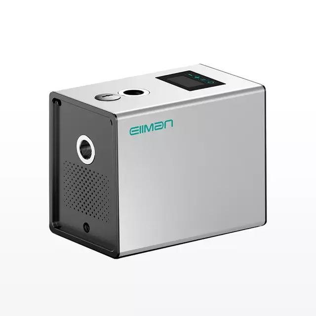
Electrical input stability connects directly to mechanical output quality. Stable power ensures steady water delivery. It also provides significant acoustic benefits. A constant pressure permanent magnet pump relies entirely on its electronic controller to translate raw power into smooth hydraulic performance. Without a stable electrical foundation, the controller cannot maintain the precise RPM required for flat-line pressure control.
Variable Frequency Drives (VFDs) act as essential voltage stabilizers. They serve as a protective buffer between grid instability and the sensitive motor. The VFD rectifies incoming AC power into a DC bus. It then inverts this DC power back into a precise, synthesized AC waveform using Insulated Gate Bipolar Transistors (IGBTs). This double-conversion process isolates the motor from minor grid fluctuations and provides a clean power supply. The DC bus acts as a shock absorber for the electrical system.
Standard VFDs cannot run permanent magnet motors effectively. The drive requires specific PMSM control algorithms. Field Oriented Control (FOC) is the industry standard for these applications. Sensorless Vector Control is another common method used when physical encoders are impractical. These algorithms manage the voltage-to-frequency (V/Hz) ratio accurately. They track rotor position continuously by measuring the back-EMF. This ensures optimal magnetic alignment between the stator and the rotor at all times.
Stable VFD control eliminates electrical humming. It reduces mechanical vibration significantly. This results in exceptionally quiet operation. You can measure the difference in acoustic performance on the job site. A properly tuned PMSM drive eliminates the aggressive whining noise associated with older PWM switching frequencies. Facilities requiring low noise levels, such as hospitals or commercial office buildings, benefit greatly from this technology. Integrated smart controllers utilize stable voltage data for advanced features. They enable IoT monitoring and predictive maintenance. Operators can track power consumption trends to anticipate mechanical wear before a catastrophic failure occurs.
Stable voltage allows the pump to maintain high efficiency at partial loads. Variable flow demand forces the pump to change speeds frequently throughout the day. A voltage-stabilized PMSM consumes far less energy than a standard induction motor under these conditions. The lack of rotor energy losses makes the difference. The drive reduces speed to match lower flow demands perfectly. The system uses only the exact amount of electrical power required to move the water, eliminating the wasted energy typical of throttled induction systems.
Engineers and procurement teams need a reliable framework to assess pump specifications. Evaluating electrical tolerances ensures long-lasting reliability. You must look beyond basic hydraulic performance curves. A high efficiency permanent magnet pump requires careful electrical vetting before installation. Always check the nameplate data on the motor and compare it against the drive's output specifications. Mismatched equipment leads to poor power factor and excessive heat.
Start by examining the input voltage range and tolerance specifications. Verify the manufacturer's stated acceptable wide-range input voltage. A heavy-duty industrial drive should handle 380V-480V with a ±10% tolerance. This flexibility prevents nuisance tripping during minor grid sags. Evaluate the pump drive's built-in protection mechanisms. Check the specific under and overvoltage trip thresholds in the technical manual. Ensure these thresholds align with your facility's historical power quality data.
Power factor correction requires careful attention during the evaluation phase. The pump's drive impacts the facility's overall power factor. Standard rectifiers in basic drives can introduce harmonic distortion back into the grid. Evaluate the need for integrated DC chokes. Consider active front-end drives for large installations. These technologies mitigate total harmonic distortion (THDi) caused by the voltage conversion process. Keeping THDi low prevents overheating in your facility's transformers and wiring.
You must balance the initial equipment premium against necessary electrical infrastructure upgrades. High-efficiency pumps cost more upfront. Installing them in a facility with poor power quality requires additional hardware. You may need to upgrade facility wiring to handle the high-frequency switching of the VFD. Adding line reactors or surge protection devices increases the installation budget. Evaluate these infrastructure requirements before finalizing the equipment selection to avoid unexpected project overruns.
Voltage Disturbance Types and Mitigation Strategies
Disturbance Type |
Impact on Permanent Magnet Motor |
Recommended Mitigation Strategy |
|---|---|---|
Voltage Sags (Undervoltage) |
Increased stator current, thermal stress, potential stalling. |
Wide-tolerance VFDs, phase monitors, voltage regulators. |
Voltage Surges (Overvoltage) |
Insulation breakdown, capacitor failure, rotor demagnetization. |
Surge protection devices (SPDs), isolation transformers. |
Phase Imbalance |
Uneven heating, severe mechanical vibration, reduced lifespan. |
Active front-end drives, dedicated phase monitoring relays. |
Harmonic Distortion (THDi) |
Overheating of facility wiring, interference with sensitive electronics. |
Integrated DC chokes, passive harmonic filters, line reactors. |
Installing PMSM pumps in less-than-ideal electrical environments presents practical challenges. You must address implementation risks proactively. Ignoring power quality issues guarantees premature equipment failure. A reliable permanent magnet water pump installation requires thorough site preparation and electrical testing.
Identify signs of poor power quality early in the project. Look for frequent brownouts or flickering lights in the facility. Measure voltage unbalance between phases using a power quality analyzer. If the grid is unstable, recommend specific mitigation hardware immediately. Isolation transformers provide an excellent buffer against severe grid fluctuations. Line reactors smooth out current spikes entering the drive. Phase monitors protect the drive from sudden phase loss, which can destroy the rectifier bridge.
Integrating new PMSM drives with legacy Motor Control Centers (MCCs) requires caution. Legacy MCCs often lack the necessary cooling for modern high-frequency drives. Assess the physical space and thermal management capabilities of existing cabinets. Ensure the new drives communicate effectively with older facility control systems. You may need to install additional cooling fans or upgrade the cabinet ventilation to handle the heat rejected by the new VFDs.
Deep-well submersible groundwater pumps present unique electrical challenges. The physical distance between the surface VFD and the submerged motor creates problems. When you pull wire for a 400-foot deep well, the voltage drop calculations become critical. You must size the wire correctly to account for the distance and the high-frequency switching of the drive. Long cable runs cause significant voltage drop. More importantly, they create voltage reflection and severe dv/dt spikes. These high-frequency spikes destroy submersible motor insulation rapidly. You must install load reactors or specialized dV/dt filters at the drive output. This hardware protects the submerged motor windings from reflected wave phenomena.
Cable Length Guidelines for Submersible PM Pumps
Cable Length (Motor to VFD) |
Electrical Phenomenon Risk |
Required Output Filtering |
|---|---|---|
Under 50 feet (15m) |
Minimal voltage drop, low risk of reflected waves. |
None typically required. |
50 to 150 feet (15m - 45m) |
Moderate dv/dt spikes, minor voltage reflection. |
Load reactor (3% to 5% impedance). |
150 to 300 feet (45m - 90m) |
Severe dv/dt spikes, high risk of insulation damage. |
Dedicated dV/dt filter. |
Over 300 feet (90m+) |
Extreme voltage reflection, significant voltage drop. |
Sine wave filter. |
Conduct a comprehensive site power quality audit using a three-phase analyzer before selecting equipment.
Request detailed pump performance curves at partial loads to verify efficiency claims against your specific flow profile.
Consult with the pump manufacturer regarding specific VFD compatibility and required control algorithms for your application.
Verify maximum allowable cable length limitations for submersible applications and size your output filters accordingly.
Install necessary line reactors or dV/dt filters to protect motor insulation from high-frequency voltage spikes.
A: Operating voltage varies by application. Residential and safe-touch pumps often use a personal safety voltage of 36V to 48V DC. Commercial and industrial models require 230V to 460V+ 3-phase AC, which must be managed via a specialized Variable Frequency Drive.
A: No. PMSMs require a variable frequency drive or an integrated smart electronic controller. The controller converts and manages the AC power, synchronizes the magnetic fields, and precisely controls the motor speed. Direct across-the-line starting is impossible.
A: The PM rotor is magnetized at all times and requires no electrical power to induce a magnetic field. This eliminates rotor copper losses, allowing the pump to maintain exceptionally high efficiency even when the VFD reduces speed to match lower flow demands.
A: A voltage drop forces the drive to pull more current to maintain the required mechanical power. This increases thermal stress, reduces overall efficiency, and can trigger the drive's undervoltage protection, shutting down the pump unexpectedly to prevent winding damage.
A: It utilizes a closed-loop control system via a VFD to adjust motor speed instantly. This allows the system to maintain steady water pressure regardless of fluctuating demand, while consuming significantly less energy than a standard induction motor running at full speed.