Views: 0 Author: Site Editor Publish Time: 2026-04-29 Origin: Site


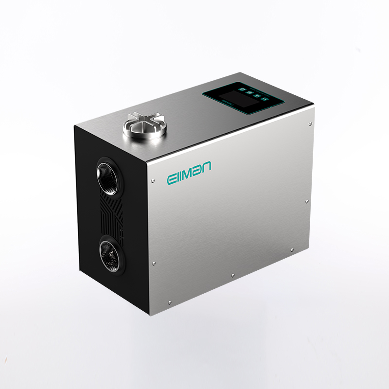
For facilities and modern residential systems facing fluctuating water demands, traditional constant-speed pumps introduce high mechanical wear and excessive energy waste. These outdated systems operate continuously at maximum capacity regardless of actual site requirements. You end up paying for unused pressure while prematurely degrading critical plumbing infrastructure. Upgrading to a modern pumping solution requires a higher initial capital expenditure but promises significant reductions in operational energy expenditure. Managing these energy costs is critical for facility operators and homeowners alike. Making an educated upgrade choice directly impacts your monthly utility bills and long-term maintenance schedules. A Permanent Magnet Variable Frequency Pump is an advanced system combining a Permanent Magnet Synchronous Motor (PMSM) with a Variable Frequency Drive (VFD). It utilizes an integrated smart controller to dynamically adjust pump speed. The technology maintains precise constant pressure or flow based entirely on real-time water demand.
Zero Rotor Loss: Permanent magnet motors eliminate the "rotor copper loss" found in traditional induction motors, achieving 95–97% motor efficiency.
Dynamic Energy Scaling: Integrated VFDs leverage pump affinity laws to drastically reduce power consumption during partial-load conditions.
Implementation Reality: Realizing the advertised ROI requires strict adherence to electrical safeguards, including sine-wave filters and proper thermal management to prevent demagnetization.
Ideal Use Cases: Best suited for environments requiring frequent start/stop cycles, variable flow rates, and precise constant-pressure delivery.
Understanding this pumping technology requires looking inside the motor casing. Standard induction motors rely on electromagnetic induction to function. The stator creates a magnetic field, inducing a current inside the rotor. This process creates an inherent "slip" between the two magnetic fields. Slip generates excess heat and wastes electrical energy. Permanent magnet synchronous motors completely shift this paradigm. Manufacturers embed rare-earth permanent magnets directly into the rotor assembly. The motor no longer needs to induce a magnetic field. The rotor spins synchronously with the stator field. You eliminate slip entirely. This direct magnetic interaction prevents energy loss and drastically reduces operational heat.
The variable frequency drive acts as the central brain of the pumping system. It continuously reads water demand and calculates the exact power required. The drive executes sensorless flux-oriented control (FOC) algorithms to maintain peak performance. Here is how the FOC algorithm operates sequentially:
The controller measures phase currents flowing into the motor windings.
It mathematical models the exact magnetic flux without relying on physical sensors.
It calculates the precise rotor position and speed in real-time.
The drive adjusts voltage and frequency outputs to optimize torque instantly.
Eliminating physical sensors increases system reliability, especially in wet environments where traditional sensors fail. Furthermore, the VFD solves a major mechanical problem: the water hammer effect. Traditional pumps start abruptly at full speed. The sudden rush of fluid slams into pipes and valves, causing severe mechanical stress. A VFD enables soft starts and smooth stops. It dynamically ramps up the permanent magnet motor variable speed to match demand gradually. You prevent sudden pressure spikes. This gentle operation reduces pipe fatigue and extends your entire infrastructure lifespan.
Evaluating an equipment upgrade requires a deep look at efficiency metrics. A standard induction motor typically tops out at 85–93% efficiency at full load. A permanent magnet synchronous motor consistently reaches 95–97% efficiency. While a few percentage points seem minor, the gap widens significantly under partial-load conditions. Standard motors lose efficiency rapidly when they operate below maximum capacity. Permanent magnet motors maintain their high efficiency curve even when running slowly. Since most water systems operate at partial loads 80% of the time, this sustained efficiency yields massive energy savings.
The true financial justification lies within the cubic law of pump power. Pump affinity laws dictate how speed relates to energy consumption. Power requirements scale with the cube of the motor speed. The math delivers compelling results for variable demand systems. If you reduce your motor speed by just 20%, you cut power consumption by nearly 50%. If you reduce motor speed by 50%, power consumption drops by up to 87.5%. The ability to scale energy consumption directly against real-time demand allows facilities to recoup costs rapidly.
Motor Speed (%) | Flow Rate (%) | Pressure Head (%) | Power Consumption (%) |
|---|---|---|---|
100% | 100% | 100% | 100% |
80% | 80% | 64% | 51.2% |
50% | 50% | 25% | 12.5% |
You must balance the initial capital expenditure (CapEx) against the reduced operational expenditure (OpEx). Permanent magnet pumps typically cost about 30% more upfront. The price premium comes from expensive rare-earth materials and complex digital controllers. However, this initial investment secures a much lower energy profile over a 5 to 10-year lifecycle. You use significantly less electricity every operating hour. The mechanical components also experience less wear due to soft starting, which lowers long-term maintenance requirements.
Certain environments extract maximum value from this technology. Commercial and high-rise water supply systems represent an ideal deployment scenario. A modern high-rise experiences wild fluctuations in simultaneous usage. Hundreds of occupants might open and close taps unpredictably. A variable frequency system reads these pressure drops instantly. It accelerates or decelerates the pump to maintain constant pressure across multiple floors. Users on the top floor enjoy the same shower pressure as users on the ground floor.
Deep well submersible applications also benefit heavily from permanent magnet technology. Borehole environments strictly limit motor size. Engineers face intense space constraints underground.
High Power Density: PM motors deliver more torque per cubic inch. You can install a higher horsepower motor inside a smaller diameter casing.
Adaptability: Underground water tables rise and fall seasonally. The VFD adjusts motor speed to handle these changing draw-down levels efficiently.
Reduced Cable Losses: Higher efficiency means lower operating currents, which minimizes power losses across long submersible cables.
Residential and specialized systems focus heavily on end-user comfort and safety. Homeowners despise loud utility equipment. Permanent magnet motors operate with ultra-low acoustic noise, often registering between 20 and 30 decibels. They remain quieter than a modern refrigerator. Specialized plumbing systems also incorporate critical safety innovations. Many bathroom and wet-environment booster pumps run on DC24V power. This low-voltage operation eliminates severe electrocution risks in household plumbing.
Deploying advanced motor technology requires strict engineering discipline. Permanent magnets remain highly sensitive to extreme heat and severe electrical overcurrent. High temperatures agitate the magnetic domains inside rare-earth materials. If the motor exceeds its thermal limits, the rotor suffers irreversible demagnetization. Adequate motor cooling is non-negotiable. Submersible applications frequently experience cooling failures if installed improperly. Water must flow past the motor housing to extract heat. If you install the pump in a wide tank or a borehole where water feeds from above, you must use a flow sleeve. The cooling fluid velocity must consistently exceed 0.5 meters per second. Failing to maintain this velocity guarantees a premature thermal failure.
Managing electrical stress is another critical installation guardrail. Variable frequency drives rely on fast-switching transistors. These components send rapid voltage pulses down the electrical lines. Engineers measure this specific electrical stress as dU/dt (change in voltage over time). Long cable runs exacerbate this problem, bouncing voltage waves back and forth. If you fail to limit these voltage peaks, the stress will break down the motor winding insulation. To protect your investment, you must install output filters. Sine-wave filters smooth the jagged VFD pulses into clean electrical curves. You should aim to keep the dU/dt stress below 500 V/μs.
Proper cable selection ensures regulatory compliance and system stability. You cannot wire a VFD system the same way you wire a basic direct-on-line pump. Electromagnetic interference (EMI) causes serious communication errors in nearby equipment. You must install EMC-shielded cables between the drive and the output filter. The shielding traps the high-frequency noise generated by the drive. Once the sine-wave filter cleans the power, the cable running from the filter down to the submersible motor can typically remain unshielded. Following these wiring guidelines prevents nuisance tripping and protects sensitive facility electronics.
Decision-makers must evaluate project parameters carefully before selecting a motor type. Upgrading is not automatically the right choice for every facility. You must align the motor technology with your specific hydraulic demands and budget constraints.
Decision Factor | Standard Induction Motor | Permanent Magnet VFD Pump |
|---|---|---|
Operating Profile | Continuous, 100% full-speed running | Variable flow, heavy partial-load periods |
Budget Constraints | Strict CapEx limits, cannot afford 30% premium | Focused on long-term OpEx reduction |
Thermal Environment | High ambient temperatures, poor cooling | Controlled environments or guaranteed fluid velocity |
Physical Space | Ample installation room available | Tight space constraints requiring high power density |
Acoustic Limits | Industrial settings where noise is acceptable | Residential or commercial areas requiring low vibration |
You should choose standard induction technology when your system requires continuous, maximum-capacity operation. If a pump runs at 100% speed all day, variable frequency control offers no mathematical benefit. Furthermore, if initial budget constraints strictly prohibit the equipment premium, induction remains a reliable fallback. Environments experiencing extreme ambient heat without access to complex cooling setups also favor induction motors. Standard windings handle heat abuse far better than sensitive rare-earth magnets.
Conversely, you should choose a permanent magnet variable frequency solution when partial loads dominate your duty cycle. Systems demanding frequent start/stop cycles extract massive efficiency gains from this technology. If your installation space dictates a need for a compact, lightweight motor, high power density becomes a primary deciding factor. Finally, projects placing a premium on minimizing acoustic noise and mechanical vibration will find induction motors inadequate compared to permanent magnet alternatives.
A Permanent Magnet Variable Frequency Pump is not a universal necessity for every fluid transfer application. However, it represents the mathematically superior choice for variable-demand systems. The massive energy reductions achieved during partial-load operations easily justify the initial equipment premium. Implementing this technology requires precision, but the return on investment is highly predictable.
Audit Your Usage: Record your current pump load profiles to identify how much time your system spends at partial capacity.
Run the Numbers: Calculate your potential energy savings using the pump affinity laws to build a clear business case.
Consult the Experts: Work with an application engineer to properly size your VFD, specify cooling requirements, and select the correct output filters.
Plan for Installation: Ensure your facility wiring meets EMC shielding standards before bringing the equipment on site.
A: No. Because permanent magnet motors lack a starting winding, they require a VFD to initiate rotation and synchronize the magnetic fields. Connecting them directly to standard line power will fail to start the motor and can cause electrical damage.
A: Most modern units feature built-in microprocessors that instantly detect under-load conditions. The controller will automatically shut down or decelerate the pump. This fast response prevents overheating, protects internal seals, and averts catastrophic rotor demagnetization.
A: Yes. The VFD must support permanent magnet motor control algorithms, such as PM sensorless vector control. Standard V/Hz drives designed for basic induction motors cannot properly track rotor position or control the magnetic flux required for rare-earth systems.